Take me home!

Radio Controlled Siku Claas Lexion 600

More general photos and stuff of this model here...

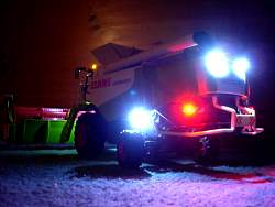
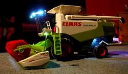
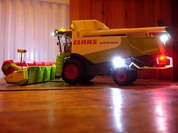
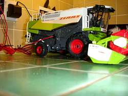
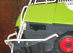
Having seen a remote controlled Claas Lexion 600 on e-Bay, I decided to have a go at making my own. Total cost including the original model was in the order of £200.00 - considerably less than the £390.00 the model on e-Bay sold for - and mine does more! I'm quite pleased with the result - this is the first radio controlled model I have built, and it really is easy! I decided to go down the RC route (as opposed to using the Siku IR control method) as RC is not line-of-sight like the Siku infra-red control. Also, the Futaba digital controller I bought, whilst not the cheapest, is fully programmable and easy to set up/tweak. A considerable amount could be saved buying a cheaper RC unit....


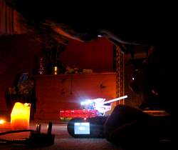
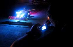
Check out the model in these videos on YouTube.com...


-------------------------------

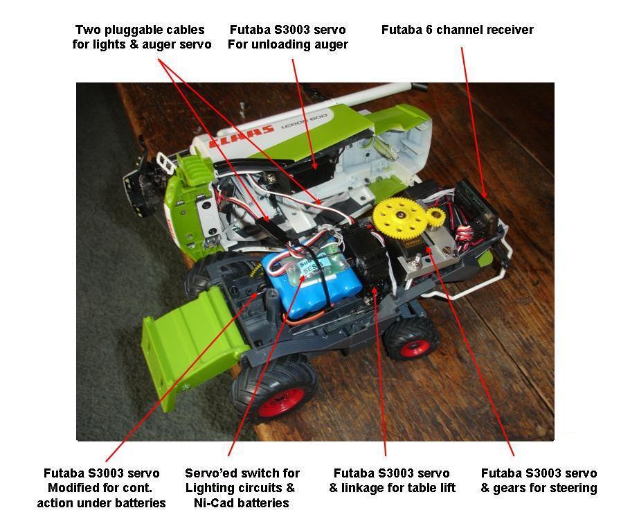
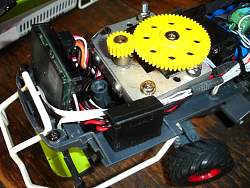
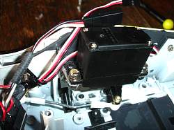
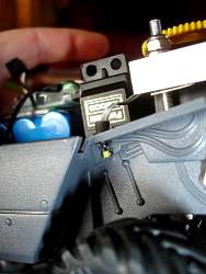
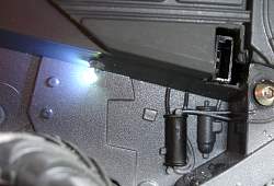
Electric and control hardware:

I used a Futaba 6EX FAAST radio setup for the model. This digital radio system allows programming of the handset to vary the end points, swing rates and mid points on all the channels. Six channels means you have control for all the necessary functions.


DSC03121.JPG
On/Off switch (foreground), Futaba receiver and steering gear details.

DSC03122.JPG
Servo and linkage for moving the unloading auger

DSC03132.JPG
Exterior On/Off switch location, easy access but hidden from view.


RC Channels/Usage:

                                 1: Forward/Reverse for the traction motor.

                                 2: Servo for steering left/right.

                                 3: Servo for cutter bar/table raise and lower

                                 4: Left flick, head/tail lights toggle on/off. Right flick, working lights toggle on/off.

                                 5: Unused/spare.

                                 6: Grain tank unloading tube/auger swing.


Lighting for the model:


                                 There are three lighting circuits as follows:

                                 1 - Two flashing amber LEDs. These come on with the main power and act as 'Power On' indicators.

                                 2 - Headlights and tail lights. These are operated using the left side of channel 4 on the Futaba controller.

                                 3 - Working lights. These are operated using the right side of channel 4 on the Futaba controller.


DSC03124.JPG
The real deal has two working lights just ahead of the rear wheels - this is the left hand side. The light is a SMD 1206 bright white LED. These whilst fiddly to solder look 'right' whilst on and off.
DSC03095.JPG
...and this is the right hand side. Also visible in the socket for the battery charger. This means that the batteries can be charged in situ. The socket is hidden under the hinged right hand side panel (as seen open in the next photo).
DSC03099.JPG
A modified 5mm amber flashing LED is used for the front and rear 'rotating' beacon, this is the rear one.
DSC03101.JPG
Tail lights are SMD 0805 red LED chips. Smaller than the 1206 chips these are even more fiddly, but look the part either on...
DSC03105.JPG
...or off. The wiring for the tail lights is concealed behind the folding arms, and designed to flex with them.
DSC03107.JPG
This is the front flashing LED and two of the 8 white LED working lights fitted to the roof of the cab.


DSC03177.jpg
Last working lights added were the two flood lights on the rear hood of the machine.
1024x768x24(RGB)
59.47 KB
DSC03194.jpg
That's just about it then! Added a few 'warning' transfers, covered the drive cog for the reel and tarted up the paint work
1024x597x24(RGB)
61.39 KB
DSC03216.jpg
The final product.
1024x768x24(RGB)
63.48 KB
DSC03245.jpg
This shows where the charging socket sits...
1024x768x24(RGB)
78.86 KB
IMG_4299.jpg
Photographing the combine
915x768x24(RGB)
55.48 KB
IMG_4304.jpg
Taking more photos.
1024x673x24(RGB)
61.43 KB